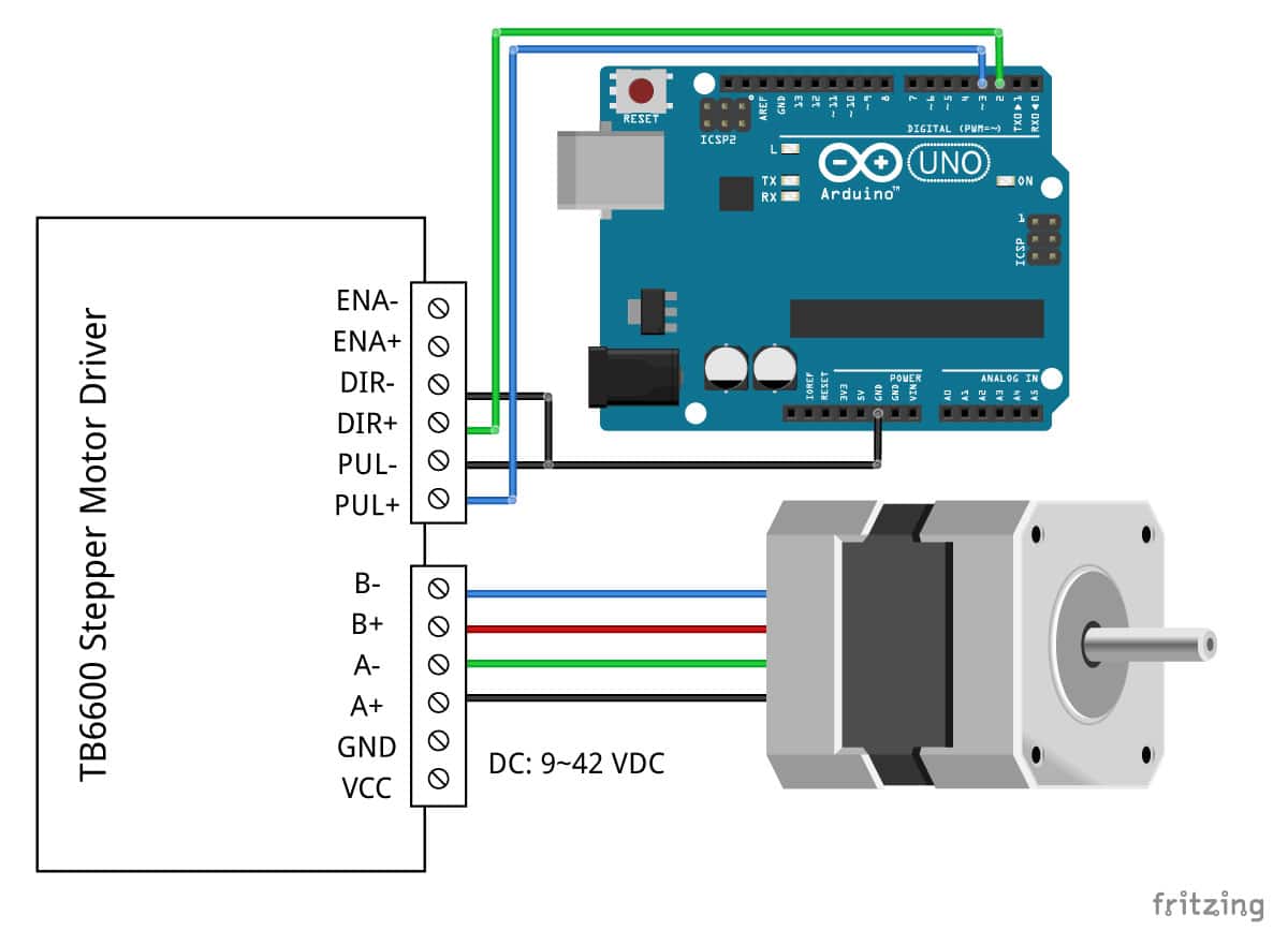

The TB6600 microstep settings can be changed by turning DIP switches S1, S2 and S3 on or off in specific order as shown in the table below. The TB6600 driver supports microstepping mode which allows higher resolutions for stepper motors by allowing intermediate step locations through energizing the motor phases with intermediate current levels.įor example, when in ½ step mode, the stepper motor will make 400 microsteps per revolution and in ¼ step mode it will make 800 microsteps per revolution. In full step mode, stepper motors normally make 200 steps per revolution which gives a step size of1.8°. A table with microstep and current settings is printed on top of the driver case. The TB6600 stepper motor driver has DIP switches used to set the microsteps and current depending on the specifications and application of the stepper motor being used. This makes controlling the driver via software easier. However, in my case ENA- is connected to ground and ENA+ is connected to a digital pin of Arduino. The enable pins (ENA- and ENA+) can be left unconnected meaning that the enable pin is always LOW and the driver is always enabled. If the multimeter shows any resistance between the wires, then that pair of wires is from the same coil. If you can still spin the shaft freely, try another pair of wires.Īlternatively, you can measure the resistance between the two wires using a digital multimeter. Then try to spin the shaft of the stepper motor and if you feel a lot of resistance, you have found a pair of wires from the same coil.

In case you are not sure which pair of wires belongs to the same coil, you can choose a random pair of wires from the motor and connect their bare ends together. Determining which wires from the stepper motor belong to the same coil. A pair of wires from one coil of the motor gets connected to A- and A+ and the other to B- and B+. Make sure that you do not connect stepper motors with a current rating of more than 3.5 A to the driver.Ī+,A- and B+,B- are the connections for the 4 wire bipolar stepper motor phases or coils.

However, they have some major differences that I’ll list in the comparison table below.
#Stepper motor arduino drivers
The TB6560 stepper motor driver can easily be confused with TB6600 model since these drivers can both be controlled using the same connections and code. Difference between TB6600 and TB6560 Stepper Motor drivers. Other specifications can differ slightly depending on the manufacturer and therefore you should always check the datasheet of your driver before use. The driver has over-current, under-voltage shutdown, and overheating protection. Also, the TB6600HG only supports up to 1/16 microstepping while the TB67S109AFTG goes up to 1/32. These chips are almost similar in performance and specifications but the TB6600HG is larger and has a higher peak current rating of up to 5A compared to the smaller TB67S109AFTG chip with a peak current rating of 4A. However nowadays many of these drivers have a TB67S109AFTG IC also made by Toshiba. The TB6600 Stepper motor driver was originally built around TB6600HG stepping motor IC made by Toshiba. TB6600 Stepper Motor driver hardware description.
#Stepper motor arduino how to
In this tutorial I’ll describe the TB6600 motor driver hardware in detail and also demonstrate how to control the driver with Arduino. The TB6600 stepper motor driver is used to control larger two-phase bipolar stepper motors like NEMA 23 motors used in 3D printers, CNC machines and robots. Example code for controlling TB6600 Stepper motor driver with Arduino using AccelStepper library.


 0 kommentar(er)
